Auto-High Frequency Reciprocating Test Rig:-
This model is a computer-controlled “FULLY AUTOMATED” reciprocating friction and wear test system which provides a fast, repeatable assessment of the performance of fuels and lubricants. It is particularly suitable for wear testing of relatively poor lubricants & diesel fuels for boundary friction measurements of engine oils, greases & other compounds. Developed by a group of Tribologists having a combined experience of over 60 years in the field of Tribology.
HFRR Applications:- |
- Evaluation of new Diesel, Gasoline & Lubricants additives.
- Determination of optimum additive dosages for raw fuels.
- Quality for outgoing products & incoming materials to ensure conformity with specs.
- Boundary friction coefficient measurements for automobile fuel economy modeling.
Operating Concept:- |
The test method measures the lubricity, or ability of a fluid to affect friction between, and wear to surfaces in relative motion under load. The system is entirely controlled by a PC via a custom electronic interface. The entire process from the loading of the specimen, attaining the temperature, achieving the required pre-defined frequency to maintaining the required defined/set load during the test duration (please note that the load tends to increase due to the heating of the specimen & the test sample), controlling the stroke length to the:-
- Measurement of frictional force.
- The calculated value of the coefficient of friction (at any particular time of friction/wear).
- Scar measurement.
is automated and controlled by the software.
All the test parameters can be pre-defined / or set manually for the test sequence and controlled by simple menu-driven control software. The software times the test and logs friction coefficient, temperature & specimen contact resistance at user-defined intervals.
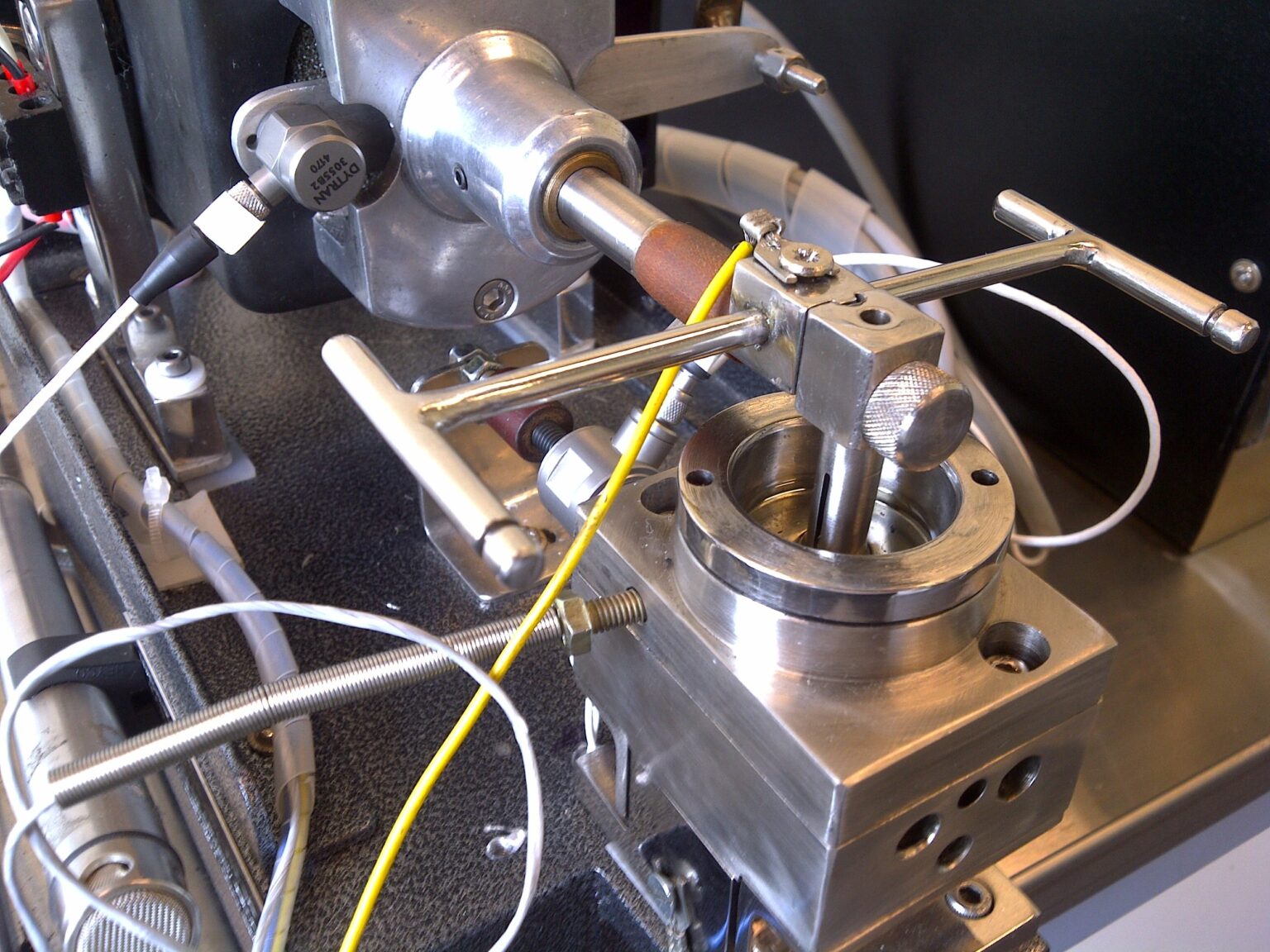
The mechanical unit uses an electromagnetic drive to oscillate the upper test ball against a fixed lower plate/disc. The digital control system and the absence of bearings and sliding components in the mechanical unit ensure absolute repeatability of stroke length and frequency. Accurate & repeatable loading is ensured by using an automated loading arrangement (not a dead weight loading arrangement used normally). Platinum RTD temperature probes are used for the specimen and safety cut-out temperature measurements. Piezoelectric transducers are used for very precise measurements of load, friction & amplitude/stroke length. Humidity probe to record the RH trace in the bath in the software.
| DATA LOGGING:- |
Collected data is displayed in a graph form during the test. It is continuously updated, saved in text format, and can easily be recalled (online during the test/offline from recorded data) and printed.
| WEAR SCAR MEASUREMENT:- |
Wear scar measurements/dimensions are done automatically (in the x, y & z axis) thru the microscope and saved in the respective test data/log file automatically for online/offline analysis.
| SOFTWARE:- |
State-of-the-art menu-driven software is used for running the tests & recording the data. The software also allows multiple temperature steps & ramps during a single test – widely used for lubricant boundary friction measurements. The software allows the user to pre-define the graphs and recall the earlier recorded test data online (real-time: during the test) for off-line analysis:
| SAFETY: |
The software controls to ensure the user-set limits to maintain the safety of the equipment and will shut down in case of any failure due to any reason.
- Mechanical Test Unit With upper and lower specimen holders, with standard test specimen/s (6mm ball and 10 mm disc).
- Data Acquisition & Control System: Controls Stroke length, reciprocation frequency, temperature, and load. Logs all test measurements to spreadsheet compatible file for printout, storage for on-line/off-line detailed analysis. This also includes IPC: C2D, LCD monitor, with all the interface hardware between PC & the test unit along with the Lazer printer.
- Microscope (for manual scar measurement).
- Humidity Cabinet – houses the test unit.
- Set of 100 test specimens.
- Extra set of Heater Cartridges.
- User instructions Manual.
- Tool Set (Allen keys).
| THE SYSTEM:- The complete system comprises: |
- Mechanical Test Unit With upper and lower specimen holders, with standard test specimen/s (6mm ball and 10 mm disc).
- Data Acquisition & Control System: Controls Stroke length, reciprocation frequency, temperature, and load. Logs all test measurements to spreadsheet compatible file for printout, storage for on-line/off-line detailed analysis. This also includes IPC: C2D, LCD monitor, with all the interface hardware between PC & the test unit along with the Lazer printer.
- Microscope (for manual scar measurement).
- Humidity Cabinet – houses the test unit.
- Set of 100 test specimens.
- Extra set of Heater Cartridges.
- User instructions Manual.
- Tool Set (Allen keys).
| SPECIFICATIONS: |
| Frequency | 5 to 200 Hz |
| Stroke Length | 20µm to 1 mm |
| Load | 0 to 200 Grams |
| Temperature | Ambient to 150°C as standard, Higher Power heaters to 250°C optional |
| CONTROL SYSTEM:- |
FunctionsControls: Stroke length, reciprocation frequency, temperature, and test duration. Allows recalling of the test data file for REAL-TIME ANALYSIS.SafetyThe software monitors & controls the defined limits
| Type | PC-based digital controller |
| Software | Custom Windows software “Tribotech Controller” |
| Data Logging | Logs, friction coefficient, temperature & % film at user-defined intervals |
| File Format | ASCII tab determined text, easily imported into any spreadsheet application |
| Electrical Supply | 110/230/240V AC, 50/60 Hz (please specify while ordering) |